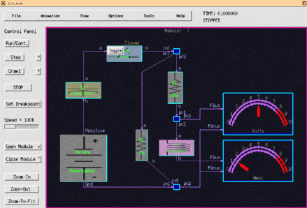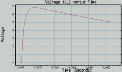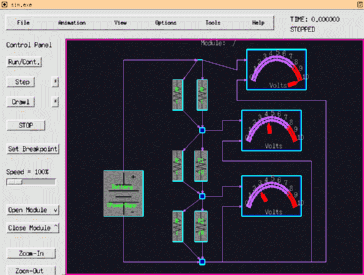
Figure 1 - Example circuit model.
Although the components may be useful as-is, they are presently considered more of a curiosity or starting-point which could be further refined, extended, and improved. The component models form examples for how to model analog elements within CSIM. With these models, many other continuous systems can be modeled. For example, thermal heat-flow modeling, mechanical systems (ex. mass/spring/damper), hydraulic, traffic-flows, as well as many other industrial applications involving inertia and proportional/differential/integro (PDI) controllers.
All the existing capabilities of CSIM can be leveraged by these models, including hierarchy, batch and interactive simulation, graphics, and automatic experiment recursion control or design value optimization. Interfacing to higher levels of system models is supported by virtue of the common environment.
Usage:
To use these models, include (by-reference) $CSIM_MODEL_LIBS/analog/Library.sim in
your top-level diagram. Draw circuits by snapping-down and connecting the components.
The components must be interconnected through junction boxes, which can be shrunk to
a virtual dot.
Most components have attributes which are specific to their function. For example, the resistor model has a resistance attribute, capacitors have capacitance, inductors have inductance, and the voltage source has a voltage setting. When you click on the attributes of each component, the appropriate attribute is listed, along with any default value and units. Set the attributes of the components to their appropriate values and click Tools/Build Simulation. If the simulation builds without errors, run the simulation.

A set of example circuit models is included in the analog_circuit model library with the prefix, test.... It is recommended to place meters on test-points of your circuits to study their behavior. Besides giving immediate readout of voltage or current, the meters produce plot files which can be plotted after the simulation with XGRAPH.

The following analog component models are provided:
|
|
|
|
|
The switch model provides interactive freedom by allowing you to throw switches while your circuit operates, and to see how your circuit responds. The examples contain demonstrations of this.
Typical applications include:
A set of icons accompanies the Analog Circuit library. The symbols are automatically attached to the components when you snap them down. Located in $CSIM_MODEL_LIBS/analog_circuits/images are the following schematic symbols:
| resistor.ppm |
capacitor.ppm |
inductor.ppm |
switch.ppm |
| battery.ppm |
diode.ppm |
zenior.ppm |
SCR.ppm |
| LED.ppm |
photodiode.ppm |
transformer.ppm |
JFET.ppm |
| MOSFET.ppm |
npn_transistor.ppm |
pnp_transistor.ppm |
Principles of Operation:
This circuit library is based on the first-principles of circuit laws from
Kirchhoff, Thevenin, and Norton, together with a convergent-relaxation method
which is distinct from the classic analytical methods applied by other tools such as SPICE.
Although virtually invisible in most
circuits, the crucial model of this library is the junction model.
All component leads must connect to a junction. And Junctions can
accommodate any number of connections. The junction model fulfills
the basic Kirkoff rule: the net sum of currents following into
and out-of a junction must be zero.
If a junction realizes a net in-flow of current (charge), it increases it's voltage until the current-sum returns to zero, and vice-versa for a net out-flow.
All other components, besides the junction, sense the voltage differentials between their leads (ports) which are set by the junctions, and they [the components] respond with current flow amounts into, or out-of, their respective leads or junction connections. For example, the resistor model senses the voltages, v1 and v2, on it's leads, and responds with current i = (v2-v1)/R out its top port, and i = (v1-v2)/R out it's bottom port.
In this way, the circuit models form a self-regulating, auto-convergent system based on a simple dichotomy which can be summarized as:
Reactive (time-varying) components, such as capacitor or inductor use their corresponding differential/integral function. For example, the inductor's governing equation for current is: i = integral( V/dt ) / L. The capacitor model is i = C * dV/dt.
Units are in basic System-International (SI) units, and their normal derived units: Seconds, Volts, Amps, Ohms, Henries, Farads. A set of convenient macros are included, which cause the RLC circuits to produce the correct time-constants.
	macro mH = * 1.0e-3
	macro uH = * 1.0e-6
	macro pH = * 1.0e-12
	macro mF = * 1.0e-3
	macro uF = * 1.0e-6
	macro pF = * 1.0e-12
	macro Kohm = * 1.0e3
	macro Mohm = * 1.0e6
This allows you to set an inductance to say, 4.3 uH, a capacitor to say, 3.3 uF, or a resistor to 6.8 Kohm.
Examples:

Issues: