WinFrame 3D Viewer Format - WFL
WinFrame Language (WFL)WinFrame Language is a simple XML application interface that can be used to drive a variety of viewers to perform interactive object animations. (Commas and quotes are optional.)
0. Coordinate System:
WinFrame operates within a Cartesian coordinate system, with coordinates X, Y, and Z. The units are arbitrary, but often are assumed to be meters, by convention. When modeling small spaces, units of millimeters, inches, or feet have been used. While for large spaces, Km or miles may be convenient.By common computer graphics convention in 2D displays, the X-axis is normally the horizontal (left-right) axis, and the Y-axis is the vertical (up-down) axis. 3D graphics extends this by adding the Z-axis, or depth-axis, which is commonly viewed as coming out of, or receding into, the screen. Note that in WinFrame, the observation point, or camera view-position, can be changed. Figure 1 below, illustrates the relationship of the axes, as viewed when the camera position is placed in the positive X-Y-Z quadrant.
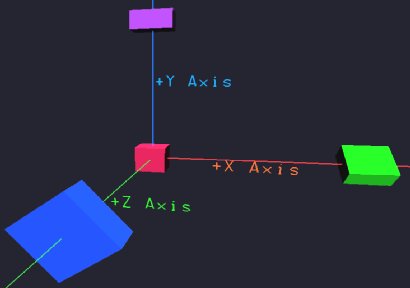 |
Figure 1 - WinFrame Coordinate Aves.
When used to view terrain-maps or outdoor landscapes, the X-axis typically represents the East-West coordinate, the Z-axis represents the North-South coordinate, and the Y-value represents (up-down) altitude.
1. Setting Camera Position, Field of View, and Aiming:
The camera setup must be done first, before anything else.

   <set_camera>
	<frustum fov="" near_field="" far_field="" />
	<position x="" y="" z="" />
	<pointat  x="" y="" z="" />
   </set_camera>

 Example:
	  <set_camera>
		<frustum fov="45.0" min="2.5" max="12000.0"/>
		<position x="0.0" y="1200.0" z="-4900.0"/>
		<pointat  x="0.0" y="0.0" z="-2350.0"/>
	   </set_camera>

  Where:  View_angle (fov=field-of-view) is in degrees.  (Frustum is the viewable volume
	  in front of the virtual camera, or viewing location.)
	  Near-field is the closest range from the camera that objects will be visible.
	  Far-field is the farthest range.
	  Convention is to assume coordinates are in meters.
          X-axis is initially left-right  (for camera position x=0 with z=negative).
	  Y-axis is up-down (positive y is up).
	  Z-axis is into screen.
	  The pointat operator specifies where the camera is pointing at.
	  Camera settings can be changed throughout simulation.
	  If unsure about these settings, experiment.  Frustum can be varied
	  interactively under the Meta-menu.


2. Defining Object Types:

  <def_obj> type_name
   ...
  </def_obj>

Where "..." is the list of components out of which the new object-type
is composed. Objects may be constructed from any combination of
triangles, quadrilaterals (quads), images, image-slices, simple objects
(lines, text, spheres, boxes, cylinders, disks), and other sub-objects.
Triangles, quads, and images are described in this section.  The other
component types are described in subsequent sections.

Triangles & Quads:

Colored surfaces of arbitrary shape can be constructed out of the basic
building blocks:  triangles and quads. The color of subsequent
triangles and/or quads is set by the <col r="" g="" b="" t=""/>
tag. In def_obj, color can be set anywhere, and remains until changed.
It should be set once before drawing triangles or quads. Color is
specified by r,g,b and t, where t is transparency (1=solid, 0=clear,
0.5=translucent, etc.), by:

   <col r="" g="" b="" t=""/>

Triangles are specified by:

   <tri> <vrt x="" y="" z="" />  <vrt x="" y="" z="" />
				<vrt x="" y="" z="" /> </tri>

Example: - Define an object out of triangular polygons.

	<def_obj> BuildingT36
	 <col r="0.19" g="0.27" b="0.28" t="1"/>
	 <tri>
	        <vrt x="118.03" y="0" z="-259.674"/>
	        <vrt x="157.36" y="0" z="-259.674"/>
	        <vrt x="157.36" y="206.467" z="-259.674"/>
	 </tri>
	 <tri>  <vrt x="118.03" y="206.467" z="-259.674"/>
		<vrt x="118.03" y="0" z="-259.674"/>
		<vrt x="157.36" y="206.467 -259.674"/>
	 </tri>
	 <tri>	<vrt x="118.03" y="206.467" z="-312.025"/>
		<vrt x="118.03" y="206.467" z="-259.674"/>
		<vrt x="157.36" y="206.467"" z="-259.674"/>
	 </tri>
	</def_obj>


Quadrilateral polygons (Quads) are specified by the <quad> construct:

    <quad> <vrt x="" y="" z="" /> <vrt x="" y="" z="" />
			<vrt x="" y="" z="" />
			<vrt x="" y="" z="" /> </quad>
Note there are four vertices per a quad. Special care must be taken,
when using quads, to not cross the vertices, like an hour-class
shape. Open GL does not support that.
A key point to note is that, by default, triangles and quadrilaterals are visible only from their front side. (This is advantageous for rendering efficiency, since many objects are viewed from only one side. For example the walls of any solid object, such as a boat or a building, as viewed from outside.) The front side is determined by the pointing direction of the vector norm of the vertices, - also called the winding. If you get the winding (order of the vertices) wrong, you may notice your triangle is viewable from the wrong side. Simply reverse the winding by flipping a pair of vertices in the case of a triangle, or by re-ordering three vertices of a quad.
A simple way to avoid the wrong-side problem is to use two-sided polygons. These are also useful when you are describing a thin surface which actually can be viewed from both sides. Use the variants <tri2> and <quad2> accordingly.
Lines:
Two points make a line.
<line> <vrt x="" y="" z="" /> <vrt x="" y="" z="" /> </line/>Optional additional tags can occur with the <line> and </line/> pair, include:
	<col r="" g="" b="" t="" />
	<thick thickness= "" />
Thickness defaults to 1.
Images/Textures:
Instead of just colored surfaces, you can define objects by mapping arbitrary images to the quadrilaterals.
This produces rich textures and realistic views, while often reducing the total polygons for drawing scenes with
better qualities.
Instead of <tri>, <col>,and <quad>; use:
  <image> image_filename  <vrt x="" y="" z="" />
		<vrt x="" y="" z="" /> <vrt x="" y="" z="" />
		<vrt x="" y="" z="" /> </image>
For examples and further information, see also More info about defining images.
Mixing Object Types:
Mixtures of <tri>, & <quad>,and <image>, as well as any of the
simple shapes (disk, box, cylinder, sphere) described below, can be all used in any combination.
Also, other object types can be instantiated within new definitions to create compound objects through hierarchical
construction.
Scaling and Offsets: Scale: <scale> SC </scale> Offset: <offset x="XX" y="YY" z="ZZ"/> Where SC is the scale amount, and XX, YY, ZZ are the offset amounts for x y, and z axes, respectively. These commands scale or offset all subsequent objects by the designated amounts. This can be used to fit objects which were defined with greatly differing sizes into common scenes. Also allows changing the centers for better rotations. Examples: <scale> 2.0 </scale> <offset x="10.0"/> <offset x="10.0" y="-30.0"/>
3. Instantiating Objects:
<inst_obj name="" kind="" x="" y="" z="" xang="" yang="" zang="" /> ... Where name sets the instance-name of the object. All object instances must have a unique instance-name. This becomes the handle to the object for future commands, such as moves, rotations, etc.. And where kind specifies the type of object to instantiate. (This must be a previously defined type-name.) And where x,y,z set the initial position, and the remaining xang, yang, and zang set the initial xAxisAngle, yAxisAngle, and zAxisAngle angles in degrees. The above is useful for instantiating the initial objects immediately. To schedule new objects to be added at later times, use inst_obj_at. <inst_obj_at name="" kind="" T="" x="" y="" z="" xang="" yang="" zang="" /> Where T is instantiation time. The rotation angles are applied in the order of zang first, yagn second, and xang last. Example <inst_obj name="Building_37" kind="BuildingT36" x="0" y="0" z="0" xang="0" yang="0" zang="0" /> Instance Scaling - <scale> SC </scale> - Affects the instantiation positions. - Is obeyed when encountered anywhere between objects. (Except within an object's definition where it is local.) - Remains set to whatever, until re-set back to 1.0. - Does not affect an instance of an object's defined size, but does scale the position values of the instantiated object. Options face="camera" - Causes object to always face camera. Good for text attached to objects. Keeps it readable from any angle. Also good for 2D animatrons, keeps 2D image or object always facing camera for simulated 3D look.
4. Moving Objects:
moveobject <mo obj="" T1="" T2="" x="" y="" z="" /> <mo_rel obj="" duration="" x="" y="" z="" /> rotateobject <ro obj="" T1="" T2="" xang="" yang="" zang="" /> <ro_rel obj="" duration="" xang="" yang="" zang="" /> orbitobject <orbity obj="" T1="" T2="" xcntr="" ycntr="" zcntr="" ang="" /> <orbity_rel obj="" duration="" xcntr="" ycntr="" zcntr="" ang="" /> <orbitx obj="" T1="" T2="" xcntr="" ycntr="" zcntr="" ang="" /> <orbitx_rel obj="" duration="" xcntr="" ycntr="" zcntr="" ang="" /> <orbitz obj="" T1="" T2="" xcntr="" ycntr="" zcntr="" ang="" /> <orbitz_rel obj="" duration="" xcntr="" ycntr="" zcntr="" ang="" /> The _rel, or relative versions of the movement commands instruct the viewer to move the object for the duration specified, beginning whenever the command is received by the viewer. These permit non-synchronized/real-time simulations to drive the viewer. They are time-relative, or relative to the current time.The moveobject command (mo) causes the named object-instance to move to the specified (x,y,z) location during the specified time duration from where-ever it was at the start of the duration. It will move at whatever velocity is required to reach the (x,y,z) point at the end of the duration.
The rotateobject command (ro) causes the named object-instance to rotate about its own x, y, or z axis to the specified angle during the specified time duration. All angles are specified in degrees. It will rotate at whatever rate is needed to rotate to specified angle in that time-duration.
The orbitobject command (orbitx, orbity, oribtz) causes the named object-instance to orbit the center-point specified by (xcntr,ycntr,zcntr), from it's initial location. The distance between the center-point and the initial location defines the radius of the orbit. It will orbit by the specified angular amount during the specified time duration. This command can be used to produce curvilinear trajectories by using angles less than 180-degrees, or can be used to produce multiple orbital passes by using angles that are many multiples of 360 (IE. much greater than 360). All angles are specified in degrees. Orbital motion can be specified relative to each axis independently. For example, orbity causes an orbit around the y-axis in which the object will move in the x-z plane. A simultaneous orbitx at the same rate will cause a y-displacement - in combination creating a slanted orbit.
5. Drawing Lines or Radio Beams:
Lines between Points in Space -
DrawLine <drawline x1="" y1="" z1="" x2="" y2="" z2="" t1="" t2="" r="" g="" b="" thickness=""/> <drawline_rel x1="" y1="" z1="" x2="" y2="" z2="" duration="" r="" g="" b="" thickness=""/>Beams between Points in Space -
BeamXYZ - (Same as DrawLine but with thickness = 3.0) <beamxyz x1="" y1="" z1="" x2="" y2="" z2="" t1="" t2="" r="" g="" b="" />Beams between objects -
Beam <beam obj1="" obj2="" t1="" t2="" r="" g="" b="" />Beam offsets -
BeamOffset <beamoffset y="" /> Raises or lowers the point that beams are drawn to/from objects (as drawn via the <beam obj1 obj2 ... command). The value offsets the attachment point in the Y-dimension (usually up/down). The beam command normally draws to an object's defined origin point. However, many vehicle object definitions start at y=0.0 (where the tires meet the road), and work upward from there. If left alone, beams will be drawn to the bottom of the object, and will often be obscured by terrain. Instead, you may wish the beam to be drawn toward the top of the vehicle, where the antenna is. Accomplish this by providing a positive Y offset. This is a global offset.Conical Beams between objects -
ConeBeam <conebeam obj1="" obj2="" t1="" t2="" r="" g="" b="" bw=""/> Where bw is the beam-width. The default value of 1.0 corresponds to a 30-degree cone-beam. Smaller values make narrower cones, and vice-versa.
6. Comments:
You may place comments within geometry files, or use the comments to comment-out sections of a geometry file. The standard XML comment construct is: <!-- whatever --> An alternate, perhaps more intuitive syntax is: <comment> whatever ... </comment>
7. Including Files:
You may reference other files from within a geometry file. The include construct is: <include> filename </include>
8. Requesting Time:
This command is intended for use from live programs connected by sockets to WinFrame3D. Often it is useful to synchronize, or have some notion as to the progress of the viewer from a simulation which may not run in real-time. For example, the simulation may either not want to get too far ahead, or fall behind the real-time clock which governs the viewer. In such cases, the interactive program can ask the WinFrame3D viewer for the time by sending the following command on the socket. <time/> WinFrame3D will respond with the current time in seconds since the start of the viewer as a floating-point number character string. This is the same time reference which governs the display (ex. T1 and T2). The string is sent back over the same socket on which the command was received. Example: { char tmpst[100]; send_soc( soc, "<time />\n"); /* Ask what time it is. */ send_soc( soc, "<nop />\n"); /* Send nop to flush socket. */ if (recv_soc( soc, tmpstr, 100 ) < 0) printf("socket error\n"); if (sscanf( &(tmpstr[3]), "%f", &Tnow )!=1) printf("error reading time (%s)\n", tmpstr);; }
9. Fog Control -
By default, fog is normally "on", it's density is set to 0.0002, and it's color is r=0.3 g=0.3 b=0.5. - Fog can controlled by the following command-line options. - Disable fog by: -fogoff or: -nofog - Increase or decrease fog-density by: -fogdensity 0.0002 - Change fog color by: -fogcolor r g b For example: -fogcolor 0.3 0.3 0.5 - Fog can be controlled within files by the following tags: - Disable fog by: <fog density="0.0" /> - Enable fog and set density to xx by: <fog density="xx" /> - Change fog color by: <fog color="r g b" /> - Fog can also be controlled interactively on the Meta-menu. See Other WF3d Command Line Options.
10. Background Color - <bgcolor r="0.3" g="0.3" b="0.6"/>
- Normally background color is r=0.3 g=0.3 b=0.6. - This command changes the background color to whatever you want. - Example: <bgcolor r="0" g="0" b="0"/> (Makes black background.)
11. Adding Text -
<text name="" x="" y="" z="" xang="" yang="" zang="" r="" g="" b="" scale="" thickness=""> YOUR TEXT HERE </text> Defines and instantiates a named text object. It can be moved, rotated, shifted, etc.. Example: <text name=textitem1 x="120" y="200" z="45" scale="10" thickness="2" r="1" g="0" b="0"> This is the text. </text> The name is required, but the other parameters are optional. Scale controls the size of the text, and defaults to 1.0. Thickness controls the thickness or boldness, and defaults to 1.0. The x,y,z values set the location of the text, relative to the lower left corner of the text string. The r,g,b values control the text color, range between 0.0 and 1.0, and default to a lime color. The xang, yang, and zang cause the text orientation to be rotated around the x, y, or z axis, respectively, by the specified angle in degrees. If the angles are set to zero or left-out, by default the string advances from left-to-right along the x-axis, and up-down along the y-axis. The rotation angles can be used to change from the default orientation, Other Options face="camera" - Causes text to always face camera. Good for text attached to objects. Keeps it readable from any viewing angle.
12. Camera Positioning -
You can move and point the camera via the following file or socket commands. These can be used to pan the camera at predetermined rates and times. <camera_move t1="" t2="" x="" y="" z="" /> <camera_move_rel duration="" x="" y="" z="" /> and <camera_point t1="" t2="" x="" y="" z="" /> <camera_point_rel duration="" x="" y="" z="" /> When modeling land areas, the camera can be restricted from going below ground level by the following tag: <camera_min_alt min_alt="yy" /> Where yy is the minimum height above the terrain. This option is primarily useful when used with a terrain-elevation surface. The camera view-point can also be restricted with the -camera_min_alt yy command-line option.
13. Removing Objects -
Removing Object Instances: <rmobj name="" T="" /> Name is the instance-name of the object to be removed. T designates the time the object will be removed. Relative times may be specified with rmobj_rel. (The time will then be interpreted relative to when the command arrived to the viewer). Example: <rmobj name="tank1" T="10.5" /> <rmobj_rel name="tank1 T="3.5" /> Removing Object Definitions: (This also removes all instances automatically.) <rmdef kind="" T="" /> Kind is the type-name of the object-definition to be removed. T designates the time the object will be removed. Relative times may be specified with rmdef_rel. (The time will then be interpreted relative to when the command arrived to the viewer). Example: <rmdef kind="Tank_T72" T="10.5" /> <rmdef_rel kind="Tank_T72" T="3.5" />
14. Spheres, Cylinders, Disks, Boxes -
Several basic geometric shapes can be quickly defined through the following convenience functions.
- Spheres can be automatically defined with the following command: <def_sphere kind="" nhemi="" radius="" nslices="" nlayers="" r="" g="" b="" transp="" /> Where: kind will be the type-name of the newly defined object type. nhemi is the number of hemispheres, and must be either 1 or 2. 2 draws a complete sphere, while 1 draws a half-sphere. radius controls the size of the sphere. nslices and nlayers control the quality and complexity of the sphere in terms of the number of polygons used to render it. These default to 10 and 8 respectively, unless specified. Generally, the smaller the sphere, the less detail is needed. Values of 8 and 6 deliver the lowest quality sphere, while values of 22 and 20 deliver ultra high quality spheres. r, g, b specify the color in values between 0.0 and 1.0. transp controls the level of transparency. A value of 1.0 is solid or non-transparent. A value of 0.0 it totally transparent or invisible. A semi-transparent sphere can be useful for illustrating the range of radio transmissions or other forms of influence. On the ground, usually only a half sphere is needed. (It's orientation may need to be rotated.) Like all object definitions, the sphere needs to be instantiated. Any number of a given type can be instantiated and moved. Example: <def_sphere kind="sph1" nhemi="2" radius="600" nslices="10" nlayers="8" r="0.2" g="0.5" b="0.1" transp="0.5" /> <inst_obj name="sp1" kind="sph1" x="300" y="400" z="0" xang="-90" yang="0" zang="0" />
- Cylinders can be automatically defined with the following command: <def_cylinder kind="" radius="" nslices="" height="" r="" g="" b="" transp="" /> Where: kind will be the type-name of the newly defined object type. radius controls the diameter of the cylinder. nslices controls the quality of the cylinder in terms of the number of polygons used to render it. It defaults to 20 unless specified. Generally, the smaller the cylinder, the less detail is needed. Values of 10-15 deliver the lowest quality cylinder, while values of 40-80 deliver high quality cylinders. Values above 100 are usually overkill. height controls the length of the cylinder. r, g, b specify the color in values between 0.0 and 1.0. transp controls the level of transparency. A value of 1.0 is solid or non-transparent. A value of 0.0 it totally transparent or invisible. 1.0 is default. All but the name are optional, and will be set to the default values unless specified. Example: <def_cylinder kind="cyltype" radius="1.0" nslices="20" height="50" r="0.2" g="0.3" b="0.1" /> <inst_obj name="cyl1" kind="cyltype" x="300" y="400" z="0" xang="-90" yang="0" zang="0" />
- Disks, Arcs, Wedges can be automatically defined with the following command: <def_disk kind="" radius="" nsegs="" fill="" thickness="" ang="" dir="" r="" g="" b="" transp="" /> Where: kind will be the type-name of the newly defined object type. nsegs controls the quality of the disk in terms of the number of polygons used to render it. fill controls the outline and interior of the disk. fill = 0 produces just the outline of the disk, or an arc. fill = 1 produces just the filled surface of the disk or wedge, with no outline. fill = 2 produces a filled and outlined disk or wedge. The default fill value is 1. thickness applies only to the optional outline, and defaults to 1.0. ang and dir apply to partial disks, which are wedges or arcs. The ang value specifies the angle subtended by the wedge or arc. dir controls which direction the wedge points, or is oriented. Both angles are specified in degrees, and default to 360 (full disk), and 0, respectively. The 0-degree direction points toward the positive x-axis. 90-degrees points toward the positive y-axis. r, g, b, transp - specify the color and transparency. Each range 0.0-1.0. Transparency of 1.0 is solid, 0.0 is invisible. All but the name are optional, and will be set to the default values unless specified. Example: <def_disk kind="disktypeA" radius="10" fill="1" r="0.3" g="0.2" b="0.1" /> <inst_obj name="disk1" kind="disktypeA" x="300" y="400" z="0" xang="-90" yang="0" zang="0" />
- Boxes can be automatically defined with the following command: <def_box kind="" length="" width="" height="" r="" g="" b="" transp="" /> All but the name are optional, and will be set to the default values unless specified. Example: <def_box kind="boxtypeA" length="10" width="20.3" height="40.1" r="0.3" g="0.2" b="0.1" /> <inst_obj name="box1" kind="boxtypeA" x="300" y="400" z="0" xang="-90" yang="0" zang="0" />
15. Scaling Instantiated Objects -
You change the scale of any instantiated object at any time by: <scaleobj name="" T="" scale="" /> Where: name is the instance-name of the object to be scaled. T is the time the scaling takes effect. and scale is the scale factor. (Greater than one make larger, less than one reduces size.) Relative times may be specified with scaleobj_rel. (The time will then be interpreted relative to when the command arrived to the viewer). You may stretch or shrink an object in one dimension using the scaleobj_x, scaleobj_y, or scaleobj_z tags as follows: <scaleobj_x name="" T="" scale="" /> <scaleobj_y name="" T="" scale="" /> <scaleobj_z name="" T="" scale="" /> These commands scale the object in the respective dimension independently.16. Attaching Objects to Other Objects -
You can attach an object to another object so that the objects move together by using the attach_obj command. <attach_obj obj="" to_obj="" t1="" t2="" xoffset="" yoffset="" zoffset="" /> This causes the first object's position to be locked to the second object's position. At time t1, the first object will snap to second object's position, if not already there, and it will move with the second object as it moves. The x,y,z offsets are optional.17. Background / Foreground State -
You can display objects in the foreground of the screen that stay in the same place on the screen regardless of where the camera is pointed. The objects in foreground mode are displayed in orthonormal projection within a 100x100x500 cube. The X-values span from 0 to 100, with 0 being on the left and 100 on the right. The Y-values span from -100 up to 0, with -100 being at the bottom and 0 at the top of the screen. ((x,y)=(0,0) is the upper left corner of the display.) The Z-values span from -100 to 400, with -100 being farthest from the camera, and 400 being closest to the camera view-point. Under the normal default mode, objects are displayed in perspective projection within a user-specified frustum. Perspective viewing renders distant objects smaller than closer objects, while orthonormal projection renders objects the same size, regardless of distance from the camera. For this reason, the foreground mode is useful for displaying text, and perhaps console (own-vehicle) displays, gauges, etc., which are to remain stationary on the screen. The foreground mode is also known as screen-relative while the normal perspective or background mode is known as scene-relative. The orthonormal foreground mode is also useful for any kind of 2D displays in general, such as 2D maps, or even 2D map overlays on a split 3D screen. To specify objects in the orthonormal foreground mode, toggle into the foreground state with: <bgfgstate state = "F"/> Then instantiate the objects, text, etc.. You can switch back to the default background state by: <bgfgstate state = "B"/> You can switch back and forth between the two states whenever needed. The bgfgstate affects only the instantiation process. Once instantiated, an object remains in the respective display state. Therefore, once an object is instantiated, it can be manipulated from either state. All of the object constructs are available likewise from both states.Notes about Format:
In old versions of WinFrame (prior to version 3.0), quotes around attribute values and attribute name identifiers were optional, and commas between attributes were allowed. However, since version 3.0, strict XML syntax is now required.See Also:
- Command-Line Options-
Several useful command-line options are available, but the commands are not part of the WinFrame Language (WFL) proper. For a summary of the available options, see: WF3d Command Line Options. - WF-3D Operating Instructions -
How to operate the WF-3D viewer. Instructions for operating WF-3D during viewing, are not part of the WinFrame Language (WFL) proper, but are contained at: WF-3D Operation. - WF-3D Object Interface -
You can link WF-3D to your own programs so that you can call WF-3D commands/operations directly, without using a socket or file interface. See WF-3D Object Interface. - Other Advanced Functions - Additional functions.
See also: WF3d